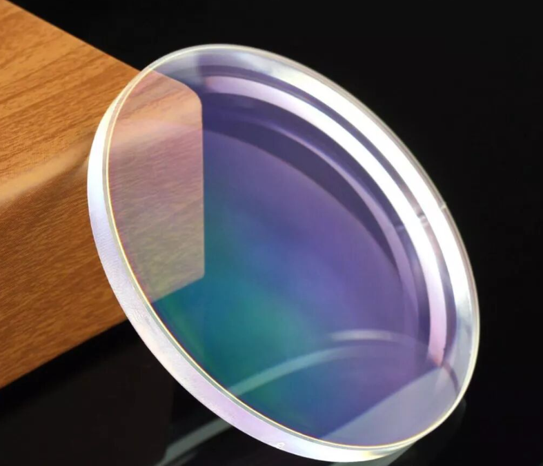
Transmittance Introduction
I. Performance Parameters
Transmittance (T) refers to the ratio of transmitted light energy to incident light energy. Reflectance (R) is the ratio of reflected light energy to incident light energy. Absorptance (A) represents the ratio of absorbed light energy to incident light energy. The mathematical relationship between the three parameters is as follows:T + R + A = 1
Absorptivity: The proportion of incident radiant energy absorbed by a substance.
Reflectance: The proportion of incident radiant energy reflected by a substance, including specular reflection and diffuse reflection.
Transmittance: The proportion of incident radiant energy transmitted through a substance.
In most scenarios, surface transmittance or reflectance is required to be measured, with clear specification of the spectral range and incident angle under actual service conditions. If polarization performance is also needed, the polarization state range shall be defined explicitly.
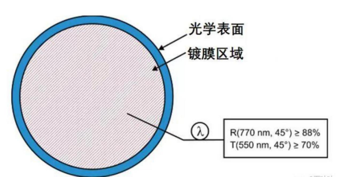
For instance, the coating specification shown in the figure below states: at an incident angle of 45°, reflectance shall be no less than 88% at 770 nm; at an incident angle of 45°, transmittance shall be no less than 70% at 550 nm.
II. Working Principle of Spectrophotometers
In practical testing, spectrophotometers and ellipsometers are the primary instruments for optical parameter measurement. Spectrophotometers measure transmittance, reflectance and absorption characteristics, while ellipsometers are used to obtain film thickness and polarization properties. The two devices share similar operating principles.
The instrument structure consists of two core modules: a beam generation channel and a beam receiving channel.
To test sample transmittance: Place the sample between the two channels so the light beam passes through the sample.
To test sample reflectance: Place the sample on the same side of both channels so the light beam is reflected off the sample surface.
The schematic diagram below illustrates how a spectrophotometer measures sample transmittance:
On the left side of the diagram lies the beam generation unit. A broadband light source emits light, which is split via a grating and filtered through a slit to output monochromatic light of a specific wavelength. The light passes through Collimator 1 to form a collimated beam, then travels through a rotatable polarizer to generate polarized light. After being converged by Collimator 2, the polarized light hits a beam splitter and is divided into two beams:
One beam is reflected to a reference detector, which captures reference light energy to correct energy drift caused by light source fluctuations.
The other beam penetrates the sample, reshaped by Collimator 3 and Collimator 4 before entering the measurement detector on the far right.
During actual measurement, two energy readings are acquired (with and without the sample). The transmittance of the sample is calculated by comparing the two energy values.
III. Transmittance Measurement
An integrating sphere is commonly adopted as the receiver to eliminate interference from reflected light reaching the detector. Its working principle is described below:
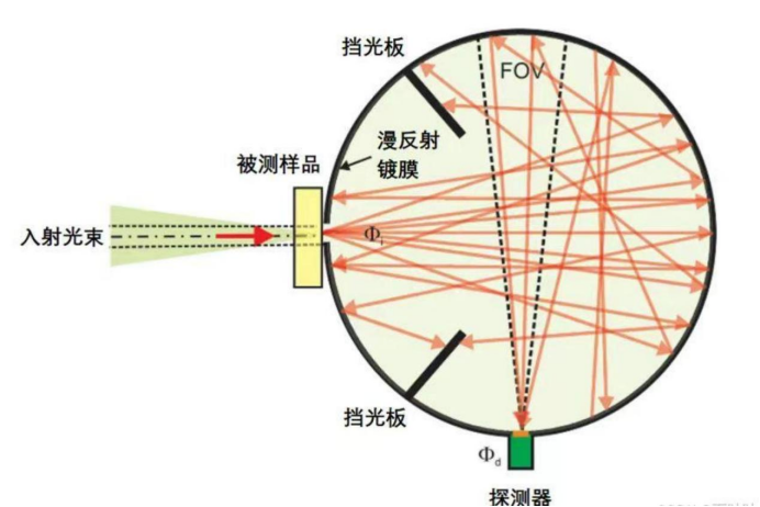
As shown in the diagram, an integrating sphere is a hollow sphere with its inner wall coated with white diffuse reflective material. Openings are reserved on the sphere wall for light incidence and detector mounting. Light entering the sphere undergoes multiple diffuse reflections on the inner coating, creating uniform illuminance across the sphere interior before being collected by the detector.
The structural diagram below shows a testing setup for measuring the transmittance of optical panels:
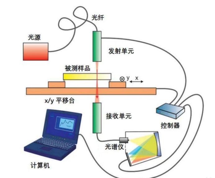
Equipped with an adjustable sample stage, the system enables transmittance testing at any position on the sample. Scanning measurement can generate a transmittance distribution map of the entire flat glass sheet, and the test resolution is determined by the beam spot size.
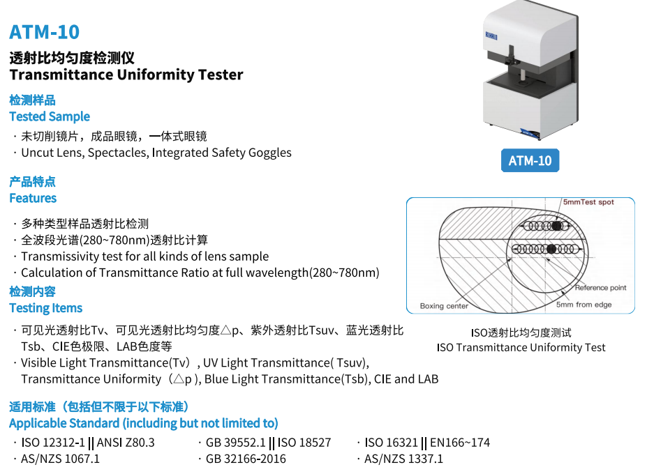
After mastering the basic principles and testing methods of transmittance measurement, how can measurement data be acquired rapidly and accurately in real production and research? This is exactly the core advantage of our ATM-10 Lens Transmittance Uniformity Tester!
ATM-10 features:
Supports transmittance testing for various sample types
Complies with transmittance inspection requirements of multiple standards
Intuitive and user-friendly software interface
Calculates full-spectrum transmittance; customizable spectral bands to meet diverse testing demands
Multi-function testing: transmittance measurement, uniformity inspection, polarized lens testing
Automatic generation of professional test reports
Perfect for laboratory research and on-line production quality control.









 2026-05-01
 Technical Paper
 Click Count:19